Guide · Snow and wind
Snow and wind loads on solar panels, from map to c/c spacing.
How closely the fixings have to be spaced comes down to two values from the map and a chain of factors. Here is the chain step by step, with a worked example and the rules in Sweden, Germany, Spain and Italy.
Updated
Two values from the map drive everything
Every load calculation starts with the site’s characteristic ground snow load and reference wind speed, read from national maps. The rest of the chain converts them into a load on this particular roof: the roof pitch, the building height, the terrain around the building and where on the roof the panel sits.
Snow presses the panel onto the roof and pulls it down the roof slope. Wind sucks the panel away from the roof, most of all at the corners and along the edges.
From map to c/c spacing, step by step
Read off snow load and wind speed for the site
Ground snow load (S0 or sk, kN/m²) and reference wind speed (vb, m/s) from the national map for the building site.
Calculate the peak velocity pressure
Choose the terrain category and take the building height (for roofs: the ridge height). That gives the characteristic peak velocity pressure qpk at that height.
Calculate the snow on the roof
Multiply the ground snow load by the shape coefficient μ for the roof pitch and by the exposure and thermal coefficients.
Divide the roof into zones
The zone width e = min(b, 2h) gives the edge zone (e/10) and the corner zone (e/10 × e/4). Each panel takes the pressure coefficient of the worst zone it reaches into.
Combine into a design load
Pressure onto the roof, uplift away from the roof and force along the roof per m² of panel, with partial factors and load combinations to the national rules.
Calculate c/c spacing and number of fixings
The fixing’s load capacity divided by the load per metre of rail gives the largest c/c spacing for each zone. The number of fixings per rail follows from the c/c spacing and the rail length.
Snow load on the roof
Sk = μ · Ct · Ce · S0 s⊥ = Sk · cos²α s∥ = Sk · cos α · sin α- Sk – snow load on the roof, kN/m² on the horizontal projection (BFS 2024:6 chapter 4, § 28).
- S0 – ground snow load from the map of Boverket, Sweden’s National Board of Housing, Building and Planning, figure 4:2 (§ 30). The map applies up to 1,500 m above sea level.
- μ – shape coefficient. For a roof without obstructions, μ1 = 0.8 up to a 30° pitch, falls linearly to 0 at 60° and is 0 on steeper roofs (SS-EN 1991-1-3, table 5.2). If snow is prevented from sliding off, for example by snow guards, μ1 is not taken below 0.8.
- Ce – exposure coefficient, at least 1.0 under BFS 2024:6 chapter 4, § 29. Ct – thermal coefficient, 1.0 as recommended in the Eurocode.
- s⊥ and s∥ – snow per m² of panel area perpendicular to the panel and along the roof slope, when the panel lies at the roof pitch α.
Peak velocity pressure of the wind
qpk(z) = [1 + 2·kp·Iv(z)] · [kr · ln(z/z0) · c0]² · qb qb = ½ · ρ · vb² w = cpe · qpk- vb – reference wind speed from Boverket’s map, figure 4:3 (BFS 2024:6 chapter 4, § 35). The map gives 20–27 m/s.
- ρ = 1.25 kg/m³. kp = 3.0 for buildings without dynamic effects, so the first bracket becomes 1 + 6·Iv. The basic Eurocode formula has 1 + 7·Iv; in Sweden the value in the regulations applies.
- Iv(z) = 1 / (c0 · ln(z/z0)) is the turbulence intensity and kr = 0.19 · (z0/0.05)^0.07. c0 = 1.0 where orography does not need to be taken into account.
- z0 and zmin by terrain category (table 4:4): 0 sea and coast 0.003/1 m, I lakes and flat land 0.01/1 m, II open country 0.05/2 m, III suburb, village or forest 0.3/5 m, IV town 1.0/10 m. Below zmin, the pressure is calculated at zmin.
- cpe – external pressure coefficient for the zone: cpe,10 for loaded areas of 10 m² and more, cpe,1 for 1 m² and less. A fixing carries roughly one square metre, so Ritwerk calculates fixings with cpe,1.
The zones on a flat roof
| Zone | Where on the roof | cpe,10 | cpe,1 |
|---|---|---|---|
| F, corner | e/4 along the edge and e/10 in from it | −1.8 | −2.5 |
| G, edge | the strip e/10 along the edge, between the corners | −1.2 | −2.0 |
| H, intermediate zone | from e/10 to e/2 from the edge | −0.7 | −1.2 |
| I, centre | the rest of the roof | ±0.2 | ±0.2 |
SS-EN 1991-1-4, section 7.2, table 7.2: flat roof with sharp eaves, zone width e = min(b, 2h). Duopitch (gable) roofs have their own tables (7.4a and 7.4b) with zones F–J. Negative value = suction.
From load to fixings
The loads are combined at the ultimate limit state. In Sweden, BFS 2024:6 chapter 3, § 6, table 3:1 applies: unfavourable self-weight γd·1.2·Gk, the leading variable load γd·1.5·Qk and other variable loads γd·1.5·ψ0·Qk. Load combination 2 is γd·1.35·Gk without variable loads. The partial factor γd is 0.83, 0.91 or 1.00 for safety classes 1, 2 and 3 (chapter 3, § 2).
Uplift is treated as a check of static equilibrium (chapter 2, § 3 and chapter 3, § 9, table 3:2), where the panel’s self-weight is favourable: the wind suction γd·1.5·w minus 0.9 times the self-weight perpendicular to the roof. The load per metre of rail is the load per m² times the rail’s tributary width. With two rails per panel, the tributary width is half the panel dimension across the rails. The largest c/c spacing is the fixing’s capacity divided by the load per metre, in each direction separately: onto the roof, away from the roof and along the roof.
Worked example: house with a gable roof, 27°
- Assumptions
- ridge 6 m, terrain II, vb 25 m/s, S0 2.0 kN/m², safety class 2
- Panel
- 1.722 × 1.134 m, 21.5 kg, portrait on two rails (tributary width 0.861 m)
- Fixing
- roof hook, uplift 2.0 kN per fixing according to the manufacturer’s datasheet
- qb = ½ · 1.25 · 25²
- 0.39 kN/m²
- qpk at 6 m height, terrain II
- 0.73 kN/m²
- Sk = 0.8 · 1.0 · 1.0 · 2.0
- 1.60 kN/m²
- Snow perpendicular to the panel, 1.60 · cos²27°
- 1.27 kN/m²
- Uplift in the corner and edge zones, cpe,1 = −2.0: 0.91 · 1.5 · 0.73 · 2.0 − 0.9 · 0.108 · cos 27°
- 1.90 kN/m²
- Uplift in the centre zone, cpe,1 = −1.2
- 1.11 kN/m²
- Largest c/c in the corner zone, 2.0 / (1.90 · 0.861)
- 1.22 m
- The same house on the coast, terrain 0 (qpk 0.98 kN/m²)
- c/c 0.89 m in the corner zone
Wind governs in the corner and edge zones. In the middle of the roof, uplift alone would allow 2.10 m, but there the force along the roof (1.85 m) and the rail’s span table (1.70 m) govern instead. The terrain around the house matters as much as the wind map: the same house gets a c/c spacing just over a quarter shorter at the corners on the coast than in open country.
The example is calculated with the same functions the designer uses. The manufacturer’s datasheet does not state whether the 2.0 kN value is characteristic or a design value, so the number of fixings is confirmed in the manufacturer’s own calculation before ordering.
How Ritwerk calculates it
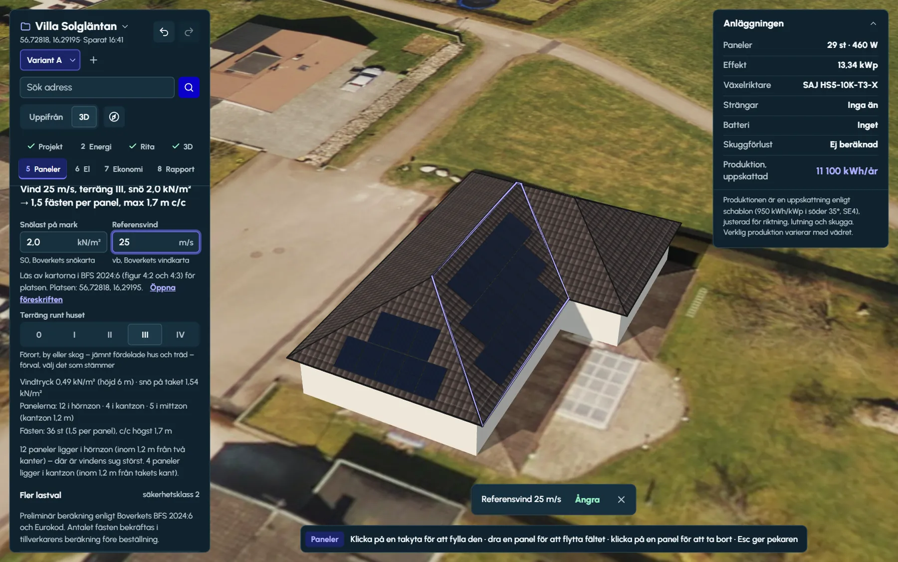
In step 5 you enter the ground snow load (kN/m²) and reference wind speed (m/s) from Boverket’s maps. The site’s coordinates are shown next to the fields, and the regulations open via a link. The terrain is chosen as 0–IV, with III as the default. Under More load options you set the safety class (default 2), snow guards on the roof and the fixing’s capacity from the manufacturer’s report.
Ritwerk takes the ridge height and the building’s dimensions from the 3D model, applies the edge zone e/10 along every edge of the roof face and marks each panel as a corner, edge or centre panel. Once the fixing’s capacity is known, from the manufacturer’s datasheet or entered by you, the largest c/c spacing per zone is calculated against pressure, uplift, force along the roof and the rail’s span table, and the smallest value governs. The result is summed up on one line with the inputs, the number of fixings per panel and the widest c/c used on any rail. The bill of materials gives the c/c per rail: for the house in the worked example, at most 1.22 m in the corner and edge zones and 1.7 m in the middle of the roof, where the rail’s span table limits it. The calculation also gets its own page in the report.
The calculation is preliminary and follows the Swedish rules: BFS 2024:6 with Eurocode 1 (SS-EN 1991-1-3 and SS-EN 1991-1-4). Other countries’ National Annexes are not applied. Ballast for racking on flat roofs is calculated in the manufacturer’s tool, for example NM Planner or SOLTOP’s Systemstatik.
In different countries
Sweden. BFS 2024:6 has applied since 1 July 2025 and replaced EKS (BFS 2011:10). The older rules could still be used if the application for building permission or the notification was submitted before 1 July 2026 (BFS 2024:14, transitional provisions, point 3). The snow map, figure 4:2, has zones of 1.0–5.5 kN/m² and is based on annual maxima for 1961–2020. Boverket’s open Klimatlaster API gives values per coordinate (version v2 = BFS 2024:6) as guidance, and the printed regulations apply.
Germany. Snow to DIN EN 1991-1-3:2010-12 with A1:2015-12 and the National Annex NA:2019-04, wind to DIN EN 1991-1-4:2010-12 with NA:2010-12. They become binding through the MVV TB (edition 2025/1) and the building law of the federal states. Snow load zones 1, 1a, 2, 2a and 3 and wind zones 1–4 are taken per municipality from DIBt’s tables, and the ground snow load is calculated from the zone according to the National Annex. In municipalities of the North German Plain that are marked in the table, buildings in snow zones 1 and 2 must also be checked for exceptional snow as an accidental action.
Spain. CTE DB SE-AE (April 2009 version) applies to buildings that require a building permit. Wind: qe = qb·ce·cp with qb = 0.5·δ·vb², δ = 1.25 kg/m³. Zones A, B and C have vb 26, 27 and 29 m/s and qb 0.42, 0.45 and 0.52 kN/m², and 0.5 kN/m² may be used as a simplification. Flat roofs have zones F, G, H and I (table D.4), and the tables of EN 1991-1-4 may be used (D.3.6). Snow: qn = μ·sk with μ = 1 up to a 30° pitch – higher than the Eurocode’s 0.8. Madrid has sk 0.6 kN/m² (table 3.8).
Italy. NTC 2018 (DM 17 January 2018) and Circolare n. 7 of 21 January 2019. Snow: qs = qsk·μi·CE·Ct with zones I-Alpina, I-Mediterranea, II and III. Up to 200 m above sea level, qsk is 1.50, 1.50, 1.00 and 0.60 kN/m², and above 200 m the value increases with altitude. μ1 = 0.8 up to 30°. Wind: vb = vb,0·ca in nine zones and p = qr·ce·cp·cd. Rome is in snow zone III and wind zone 3 (Lazio), with vb,0 = 27 m/s.
Sources
- Boverket: BFS 2024:6, regulations and general recommendations on load-bearing capacity, stability and durability in buildings, etc. – checked 14 November 2026
- Boverket: BFS 2024:14, transitional provisions (BBR 31) – checked 14 November 2026
- Boverket: Snölaster, snow loads (PBL kunskapsbanken) – checked 14 November 2026
- Boverket: Klimatlaster, climate loads (open data) – checked 14 November 2026
- European Commission (JRC): EN 1991-1-3 snow loads and EN 1991-1-4 wind actions – checked 14 November 2026
- DIBt: MVV TB 2025/1 – checked 14 November 2026
- DIBt: Technische Baubestimmungen (the tables of snow and wind zones per municipality) – checked 14 November 2026
- Código Técnico de la Edificación: DB SE-AE – checked 14 November 2026
- BOE: Real Decreto 314/2006 (CTE), consolidated text – checked 14 November 2026
- Gazzetta Ufficiale: DM 17 gennaio 2018, NTC 2018 (S.O. n. 8) – checked 14 November 2026
- Gazzetta Ufficiale: Circolare 21 gennaio 2019, n. 7 C.S.LL.PP. – checked 14 November 2026
- Weland Stål: product datasheet PD5119, roof hook fixing (version 1 – 241111) – checked 14 November 2026
Questions and answers
Questions and answers
Where do I find the snow load and wind speed for an address in Sweden?
In BFS 2024:6: the ground snow load in figure 4:2 and the reference wind speed in figure 4:3. There is no longer a table per municipality. Boverket’s Klimatlaster API gives values per coordinate as guidance. In Ritwerk you enter the values in step 5, where the site’s coordinates are shown next to the fields.
Why do the panels at the corners need more fixings?
Wind suction is greatest at the corners and along the edges. On a flat roof, cpe,1 is −2.5 in the corner zone and −1.2 in the intermediate zone – roughly twice the suction. The zone width e = min(b, 2h) determines how far in the zones reach, so a larger building has wider edge and corner zones.
Which terrain category should I choose for a house?
Residential areas, villages and forest are terrain category III. Open country with isolated obstacles is II, and the sea or a coast facing the open sea is 0. The choice matters a great deal: with vb 25 m/s and a height of 6 m, qpk is 0.49 kN/m² in terrain III, 0.73 in terrain II and 0.98 in terrain 0.
Is the designer’s calculation enough to order fixings?
No. Ritwerk gives a preliminary calculation to BFS 2024:6 and Eurocode 1 and shows the number of fixings and the c/c spacing per zone. The number is confirmed in the manufacturer’s calculation before ordering, and ballast for racking on flat roofs is calculated only by the manufacturer.
Read next
- Mounting and loadsSnow and wind loads to BFS 2024:6: wind zones, fixings per panel and the largest c/c spacing per roof face.
- Panels and mounting systems per roof facePanel arrays per roof face, flush, east–west or south-facing, with mounting system and bill of materials.
- East–west or south on flat roofsMore kWp per m² or more kWh per kWp – the comparison with figures for four locations, ballast, walkways and fire safety.
Try it on a real roof.
The designer opens in your browser, with no account. Search for an address and start drawing.