Feature · Mounting and loads
Fixings calculated for snow and wind.
Enter the ground snow load and reference wind speed for the site. The designer calculates the load zone by zone across the roof and gives the number of fixings and the largest c/c spacing for the chosen mounting system.
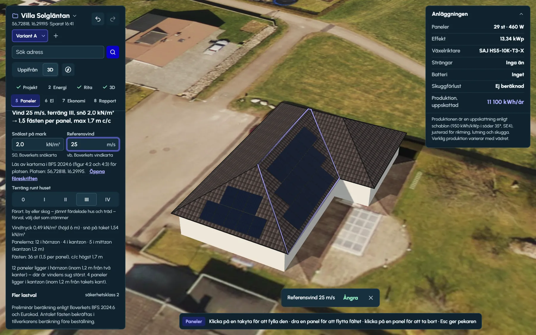
From the site to the fixing
The site
BFS 2024:6 gives the ground snow load (S0) and reference wind speed (vb) as maps, figures 4:2 and 4:3. Read them off for the site and enter the values; the designer shows the site’s coordinates and a link to the regulations.
Terrain and height
Choose terrain category 0–IV, with III (suburb, village or forest) as the default. Together with the height of the house to the ridge, this gives the peak velocity pressure qp under chapter 4, § 38, with the terrain category’s values from § 39.
The roof
The roof pitch gives the snow load on the roof – ground snow load times the shape coefficient, 0.8 up to 30 degrees – and the pressure coefficients for wind suction and pressure under SS-EN 1991-1-4, section 7.
The panels
Each panel is calculated with the worst zone it reaches into: corner, edge or centre.
The load combination
Self-weight, snow and wind are combined in the ultimate limit state under chapter 3, with the factor for the chosen safety class.
The fixing
The loaded width of the rail and the load capacity of the fixing give the largest c/c per zone and the number of fixings per rail.
What the calculation is based on
- BFS 2024:6
- Boverket’s regulations, with SS-EN 1991-1-3 for snow and SS-EN 1991-1-4 for wind – the Swedish application, without other National Annexes
- e/10
- width of the edge zone along the edges of the roof face
- e/10 × e/4
- the corner zone where two edges meet
- 3 directions
- the fixing is checked towards the roof, in uplift and along the roof
The result per roof face
A line at the top sums up the project: wind, terrain and snow, followed by fixings per panel and the largest c/c. For the selected roof face you see the wind pressure, the snow on the roof, how many panels lie in the corner, edge and centre zones, and the number of fixings with their c/c.
The zone width e is the smaller of the building’s largest dimension and twice its height. The zones run along every edge of the roof face – eaves, ridge and gable – and a panel that reaches into a zone is calculated with that zone’s load. Panels in the corner and edge zones are highlighted, because wind suction is greatest there.
The designer warns when the site’s snow load is higher than the mounting system is rated for, and when the uplift per end clamp exceeds the clamp’s capacity. Values far outside Boverket’s maps – a ground snow load above 10 kN/m² or a reference wind speed outside 20–30 m/s – are not accepted, and the field refers you to the map.
Load capacity of the fixing
The number of fixings is calculated once the capacity per fixing is known. For Weland fixings there are values from the manufacturer’s datasheets, marked preliminary because the datasheets do not state whether they are characteristic or design values. Nordmount publishes no values per fixing; there you enter the capacity in uplift, towards the roof and along the roof from the manufacturer’s report, and the number is then calculated.
The largest c/c is the capacity of the fixing divided by the load per metre of rail, in all three directions, and it does not exceed what the rail’s own span table allows. The number is calculated per rail from the c/c for the rail’s worst zone, and the spacing is kept no wider than the manufacturer’s published c/c.
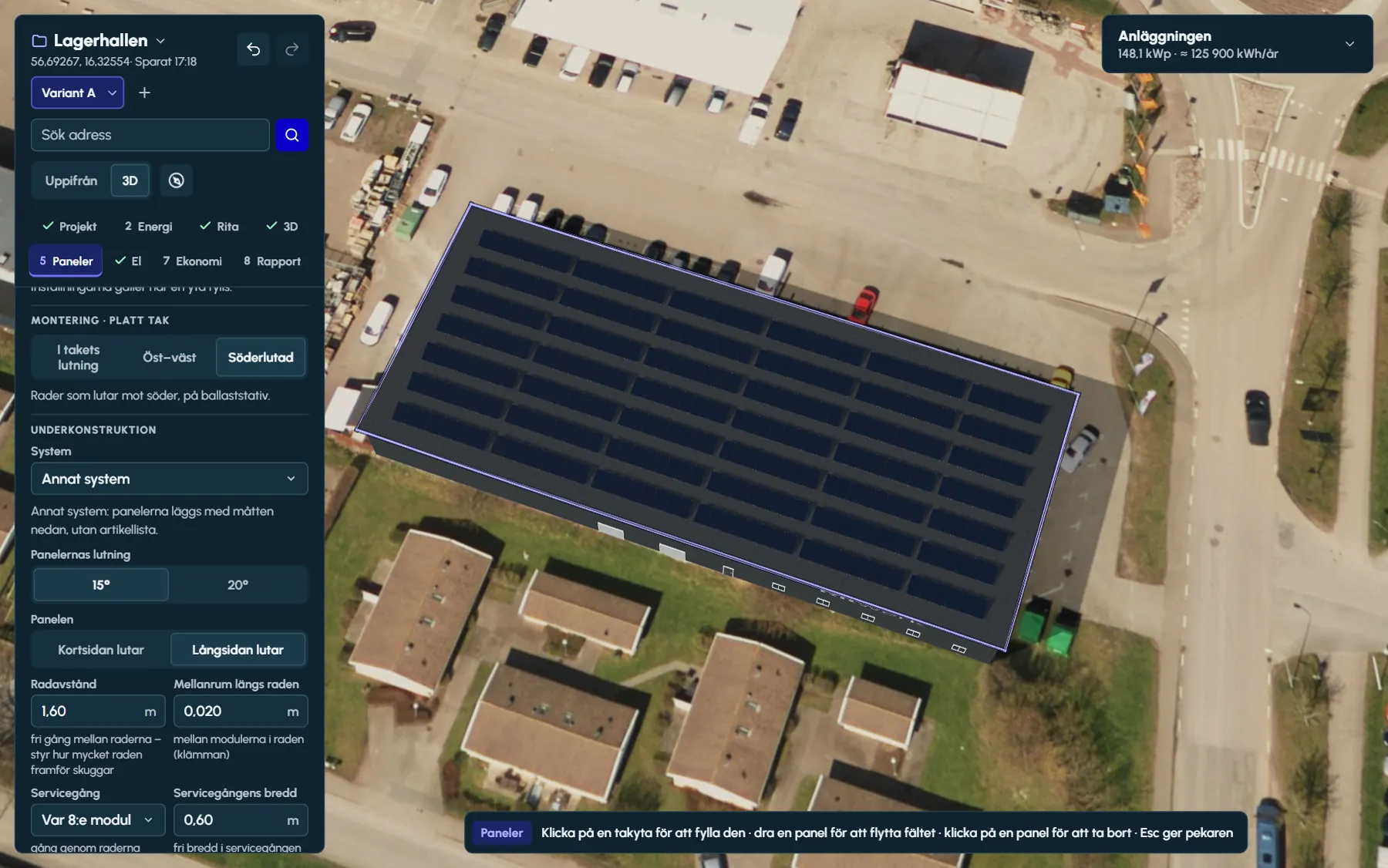
Racks on flat roofs
For east–west and south-facing racks the designer calculates wind pressure, snow and zones and shows where the panels sit. Ballast, however, is calculated by the manufacturer: NM Planner for Nordmount, SOLTOP’s Systemstatik and Weland’s calculation software. The racks’ own pressure coefficients are not published, so the designer does not derive them itself.
The flag on the roof face says which program applies, and that the panels in the edge and corner zones need the most ballast.
More load options
- Safety class 1, 2 or 3 – default 2, the class that one- and two-family houses may be assigned to (BFS 2024:6, chapter 2, § 6)
- Snow guards on the roof: the snow does not slide off, and the snow shape coefficient is at least 0.8
- Load capacity per fixing from the manufacturer’s report, which takes precedence over the catalogue values
- Every choice is a step you can undo, and the panels stay where they are
In the report and the bill of materials
At the report’s full level, the loads get a page of their own: the inputs (ground snow load, reference wind speed, terrain, safety class and panel weight), how the calculation works, a table per roof face and the design load per zone with c/c for the fixings. The page ends with the assumptions behind the calculation.
In the bill of materials, the fixing line is calculated from the load, with two screws per fixing, and marked preliminary with a note to confirm the number in the manufacturer’s calculation before ordering. Without snow and wind, or without a known capacity, the fixings are listed as "per calculation".
The calculation assumes that the roof and its load-bearing parts (battens, sarking boards, trusses) can carry the loads, that the fixings are installed to the manufacturer’s instructions and that the snow load, wind and terrain are correct for the site.
Questions and answers
Questions and answers
Does Ritwerk look up the snow load and wind for the address?
No. BFS 2024:6 gives the ground snow load and reference wind speed as maps, with no table per municipality. You read the maps for the site and enter the values in step 5. The designer shows the site’s coordinates and a link to the regulations.
Does the designer calculate ballast for flat roofs?
No. Wind pressure, snow and zones are calculated for racks too, but ballast is calculated in the manufacturer’s software – NM Planner for Nordmount, SOLTOP’s Systemstatik and Weland’s calculation software – because the racks’ pressure coefficients are not published.
Which wind zones does the designer use?
Corner, edge and centre. The zone width e is the smaller of the building’s largest dimension and twice its height; the edge zone is e/10 wide along the edges of the roof face and the corner zone is e/10 × e/4 where two edges meet. A panel is calculated with the worst zone it reaches into.
Can we order using the designer’s number of fixings?
The number is preliminary. Confirm it in the manufacturer’s calculation software before ordering – the line in the bill of materials and the report say which program applies.
Does the calculation follow EKS?
It follows BFS 2024:6, which has replaced EKS, Boverket’s earlier Eurocode application rules. BFS 2024:6 has applied since 1 July 2025, and on its own since 1 July 2026. Where it makes no choices of its own, SS-EN 1991-1-3 and SS-EN 1991-1-4 are used. Other countries’ National Annexes are not applied.
Read next
- Snow and wind loads on solar panelsFrom ground snow load and reference wind speed to load per m², wind zones and the c/c spacing of fixings.
- East–west or south on flat roofsMore kWp per m² or more kWh per kWp – the comparison with figures for four locations, ballast, walkways and fire safety.
- Ritwerk vs Solar-PlanitThe wholesaler’s no-cost tool with structural calculations for novotegra, against a solar designer with loads for several systems.
- Ritwerk vs PV*SOL premiumA Windows program with a large database versus a browser-based solar designer with the loads in the drawing.
Try it on a real roof.
The designer opens in your browser, with no account. Search for an address and start drawing.